When designing or selecting a Litz wire for use in a winding, it is important to understand and minimize skin effect and proximity effect losses wherever it is possible to do so. The uneven distribution of current in a Litz wire conductor, due to skin effect and proximity effect losses, increases the overall resistance in an AC circuit. The purpose of this article is to briefly explain skin effect and proximity effect losses and what can be done to minimize them. For more advanced reading on the subject, see the works of Sullivan and Zhang referenced in the bibliography.
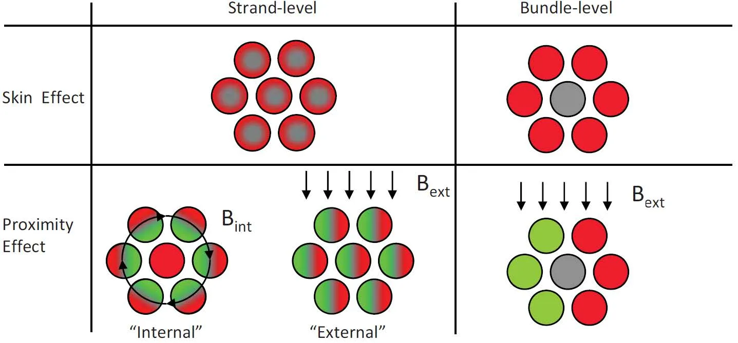
Skin effect is the tendency for current in an AC circuit to flow primarily on the outer edge of a conductor. Proximity effect is the tendency for current to flow in other undesirable patterns, such as loops or concentrated distributions, due to the presence of magnetic fields generated by nearby conductors. Skin effect and proximity effect losses can be further broken down into losses occurring at the strand level and losses occurring at the bundle level. Below is a conceptual illustration showing the effect that strand-level and bundle-level skin and proximity effect losses have on the current flowing within a Litz wire conductor.

Note that the current distributions shown are not realistic for the wire construction shown, but instead show what would hypothetically happen if only the effect being illustrated were in effect and the others were magically turned off.
Source: C. R. Sullivan and R. Y. Zhang, “Analytical Model for Effects of Twisting on Litz-Wire Losses”
Minimizing Skin Effect Losses:
With proper Litz wire design, it is possible to minimize both types of skin effect losses. Strand level skin effect losses can be minimized by selecting an individual strand size whose diameter is smaller than two times the skin depth at the operating frequency, or the effective frequency in the case of non-sinusoidal currents. See the first equation below for calculating the skin depth.
Minimizing bundle level skin effect losses is a bit more complicated. Bundle-level skin-effect losses become significant when the diameter of the overall Litz conductor is greater than two times the skin depth. When that is the case, bundle-level skin effect losses can be minimized by breaking the Litz conductor up into smaller bundles and twisting those smaller bundles together in specific arrangements.
To determine if it is necessary to break a Litz conductor up into smaller bundles you must first calculate the maximum number of strands that should be bunched in a single operation. Sullivan and Zhang1 developed the following equation (see equation 2 below) for calculating the maximum number of strands n1,max that can be bunched in a single operation before the diameter of the bundle exceeds two times the skin depth.
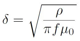
Eq. 1
δ = Skin Depth (m)
f = frequency (Hz)
Eq. 2
ρ = Resistivity of conductor material (Ω*m)
μ0 = permeability of free space (4×10⁻⁷π H/m)
ds = Diameter of an individual strand (m)
Equations 1 & 2: Calculating the skin depth and the maximum number of strands that should be bunched in a single operation for Litz Wire
Source: C. R. Sullivan and R. Y. Zhang, “Simplified Design Method for Litz Wire”
When the number of strands in the Litz conductor exceeds n1,max, the Litz conductor should be broken up into smaller bundles. In addition, stranding operations after the initial bunching step should utilize groups of 3, 4, or 5 bundles or sub-bundles. These groupings result in a configuration where no bundle or sub-bundle ends up in the center of the overall conductor or in the center of a larger bundle.
Some engineers in the industry reading this article may be wondering, “What about Litz conductors that have groups of 6 or 7 bundles?” Those stranding configurations are not uncommon with older Litz products and designs, but they are not the optimal stranding configurations in terms of electrical performance. A group of six bundles with nothing in the center is mechanically unstable, and that configuration will eventually collapse with one of the bundles will slipping into the center of the conductor. This results in a configuration of 5 bundles around 1. A group of seven bundles will naturally have one bundle in the center, forming a concentric configuration. The center member in both of those configurations will carry less current than the members in the outer layer of the conductor, due to skin effect losses at the bundle level. It is possible to include an inert filler in the center a Litz conductor having six (or more) bundles, but this will add to the cost of the product and make the termination process more complicated. Typical Type 1 and Type 2 Litz conductors are built without such fillers.
Minimizing Proximity Effect Losses:
It can also be possible to minimize the proximity effect losses in a Litz wire with the selection of an appropriate lay length for the overall Litz conductor. Depending on the overall length of the winding, shorter or longer lay lengths may be advantageous.
For windings with many turns (n>6), the overall length of the winding will typically be long enough such that strand-level proximity effect losses will dominate. Longer lay lengths for the overall conductor may be slightly advantageous in these cases. In cases where the overall length of the winding is long, tighter lay lengths would result in increased strand-level skin effect losses and higher twist loss in the overall conductor, which increases its DC resistance.
For windings with few turns (n≤6), proximity effect losses can dominate if the lay length of the conductor is not short relative to the overall length of the winding. In such cases, a shorter lay length can help to minimize bundle-level proximity effect losses.
For more on this topic, see “Analytical Model for Effects of Twisting on Litz-Wire Losses” by Sullivan and Zhang2.
Conclusion:
Optimal Litz wire performance can be achieved by designing your Litz wire conductors in such a way as to minimize skin and proximity effect losses. This can be done by limiting the number of strands that are bunched in a single operation, sticking to groups of 5, 3, or 4 bundles when conductors are stranded in multiple operations, and by selecting an appropriate lay length for your particular winding based off of the overall length of the winding.
Thanks are due to Sullivan and Zhang for their research and technical contributions to the industry’s knowledge of Litz wire. Their works on the subject no doubt helped to make this article possible.
Need a Litz wire product designed for your unique application? Contact our knowledgeable sales and engineering teams to discuss your application at [email protected] or +1(970) 351-6100.
References
- C. R. Sullivan and R. Y. Zhang, “Simplified design method for litz wire,” 2014 IEEE Applied Power Electronics Conference and Exposition – APEC 2014, 2014, pp. 2667-2674, doi: 10.1109/APEC.2014.6803681.
- C. R. Sullivan and R. Y. Zhang, “Analytical model for effects of twisting on litz-wire losses,” 2014 IEEE 15th Workshop on Control and Modeling for Power Electronics (COMPEL), 2014, pp. 1-10, doi: 10.1109/COMPEL.2014.6877187.
- C. R. Sullivan, “Optimal choice for number of strands in a litz-wire transformer winding,” in IEEE Transactions on Power Electronics, vol. 14, no. 2, pp. 283-291, March 1999, doi: 10.1109/63.750181.
You May Like
The Different Test Methods Used for Electric Strength and Breakdown Voltage Testing on Winding Wires
There are three different test methods used for Electric Strength testing and Breakdown Voltage testing on winding wires. This article will give a brief description of each test method and outline the sizes of winding

Insulated Winding Wire 101: Selecting an Insulated Winding Wire Part I: Temperature Ratings
When designing or selecting an insulated winding wire for use in a wound component, it is important to consider the following: What is the range of operating temperatures that the product will see in your