Insulation walls on insulated winding wires are much thinner today than they were in decades past. As the power electronics industry has sought to reduce the size of their components, winding wires have gotten smaller to accommodate the smaller package sizes. The reduction in size was achieved by reducing insulation walls. That reduction in insulation walls also comes with some consequences, and a greater susceptibility of the wires to physical damage during the winding and termination processes is one such consequence. The physical properties of the insulation materials have remained the same, but insulation walls have shrunk from .003” to .005” (0,076mm to 0,127mm) per layer down to .001” to .0015” (0,025mm to 0,038mm) per layer in some cases, meaning that the insulation layers experience higher stress when the same amount of force is applied. If that stress is high enough, it can result in a tear or other mechanical failure in the insulation material.
So, acknowledging that, let’s have a look at some common sources of damage to insulated winding wires:
Sharp edges and other sources of abrasion in the wire path:
As with any component, insulated winding wires can be damaged in subsequent processing. Bobbin winding processes, especially those done at high speed, are a common source of damage to insulated winding wire products after shipping. Any sharp edges or abrasive surfaces in the wire path can be potential sources of damage to the wire.
Insulated winding wires are required to be free of pin holes per UL 2353, so if you find scrapes, cuts, nicks, or thin spots in the insulation of a UL OBJT2 product after your winding process, then you need to look at your winding process for possible sources of abrasion or other types of mechanical damage. The entire wire path should be examined for sharp or abrasive contact points, and if any are found, those issues need to be corrected.
Sharp corners / sharp edges on a bobbin
Anyone who has ever banged a knee or an elbow against a sharp edge on a desk or a countertop knows firsthand why sharp edges and sharp corners are bad. The sharp corner / sharp edge makes the injury worse because it concentrates a lot of force onto a very small area of contact. A rounded or chamfered edge, on the other hand, can help to reduce the damage by spreading the force out over a larger area, resulting in a lower applied stress.
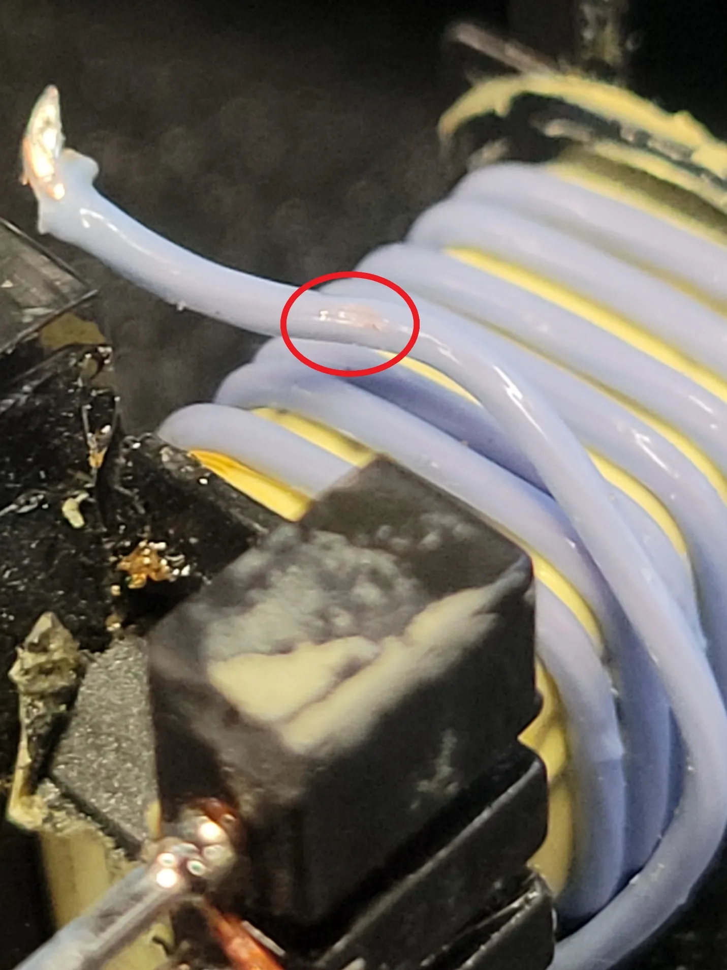
The same logic is true for the surfaces of a bobbin in a wound component that a winding wire makes contact with. Sharp edges are anathema to thin insulation walls, and they have the potential to damage and/or abrade the insulation and even expose the conductor on an insulated winding wire. Below are some pictures where the damage from a sharp edge on a bobbin was severe enough to expose the conductor.
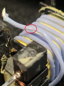
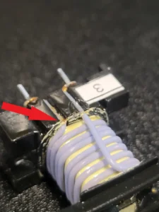
So, how can damage like this be avoided? Simple: Any sharp edges that will be in direct contact with the wire should be rounded off. Rounding the edges off will reduce the risk of scrapes or other damage to the insulation. This may have an impact on creepage distances on the transformer, so it is important to address the risk of damage from sharp corners while still in the design phase.
Sharp bends
This probably won’t come as a surprise, but sharp bends are never good for wires. They can result in broken strands in the conductor, and they put a lot of stress on the insulation. In some cases, the insulation may even buckle if the wire is bent sharply enough, especially in the case of a tape-wrapped wire. Wires with extruded insulations tend to perform better in applications where sharp bends are necessary, but even extruded insulations have their limits.
In the mechanical engineering world, engineers are taught to avoid sharp 90-degree bends in the components that they design in order to avoid large stress concentration factors in those components. A stress concentration factor quantifies how concentrated the stress is in the highest stress region within the part, due to its geometry. Parts with sharp 90-degree bends in them are considered to have a stress concentration factor of 4.35 at the corner, meaning that the stress at the corner of the component is about 4.35 times higher than the average stress throughout the rest of the component.
In wire terms, this means that the copper and the insulation both see significantly higher stresses wherever sharp bends are made. This can lead to mechanical failure in one or both. If you have ever seen a cordset or charging cable where the jacket has been damaged where the cable enters the strain relief, exposing the insulated conductors, that’s a perfect example of this type of damage. A sharp bend in the wire at the entrance to the strain relief would be the most likely cause of the failure.
Excessive winding tension:
Copper is a fairly soft metal, and it doesn’t take much force to stretch an annealed copper wire. Since conductor resistance has a direct impact on the losses in a transformer or other wound component, it is very important to avoid stretching the wire(s) in the winding process. Any stretching of the wire will result in an increase in DC resistance, and thus an increase in the AC resistance. Annealed copper typically has a yield strength between 6,500 and 10,000 PSI (45 to 69 MPa), and copper wires will stretch permanently if the applied winding tension exceeds the yield strength of the annealed copper metal. If you are unsure of what the appropriate winding tension for your wire is, reach out to the manufacturer for their recommendations on winding tensions.
Exposure to excessively high temperatures:
Excessively high temperatures can rapidly age or even melt an insulation material if temperatures are high enough. While any exposure to an excessive temperature can be enough to cause a problem, the most common source of issues that we see is with reflow soldering operations. Lead-free reflow soldering applications can see temperatures of 260°C or more and can potentially soften and/or melt ETFE or FEP insulations. For reflow soldering applications, we recommend PFA for the insulation material because it can withstand the high temperatures involved.
For other applications where exposure to high temperatures may be a concern, you should reach out to your supplier to determine if the insulation material can withstand the in-process temperatures that the product will be exposed to during further processing.
Need a winding wire product designed to fit your unique application? Would you like some help with figuring out what winding wires can give you the desired number of turns in your winding window? Contact our knowledgeable sales and engineering teams to discuss your application at [email protected] or +1(970) 351-6100.